Sodera LE Conductive Testing
Test Equipment
While exact conductive test setups are dependent on the specific circumstances surrounding the DUT RF interface, the following equipment is required for all testing situations.
- Coaxial cable with adapter for connecting to DUT 1.
- Coaxial cable with adapter for connecting to DUT 2.
- Coaxial T-connector.
- SMA adapters for connecting coaxial cable or attenuators to the Sodera LE Antenna and Wireded connectors.
- Attenuators, values depending on the Bluetooth technology or Class being tested.
-
Frontline Sodera LE Wideband Bluetooth low energy Protocol Analyzer.
- Personal computer for running Frontline software.
Test Setup
The following figures show the conductive test setup. The values of AT1, AT2, and AT3 depend on the power transmitted by DTU1 and DTU2 and which setup is used.
Note: Internal Sodera LE attenuation options are likely to preclude the use of external attenuators when using typical Bluetooth low energy power levels.
Wired Input Test Setup
"Sodera LE Conductive Test Setup (a)" connects the test signal to the Sodera LE Wired input connector. This input provides internal 27 dB attenuation, so AT3 may not be necessary depending on the DUT1 and DUT2 transmitted power.

The AT1 through AT3 attenuator values will depend on the DUT 1 and DUT 2 transmitter Class or the transmit power from each device. At higher power levels all three attenuators may be needed. In all cases, use good engineering practices to protect the devices under test and the Sodera hardware from damage, and to ensure reliable operation.
For example, assume that there is no attenuation in the test setup (a): At the T-connector the power will split in half. For example, if DUT 1 is transmitting +20 dBm (100 mW), at the T-connector it will split with +17 dBm (50 mW) going to DUT 2 and +17 dBm (50 mW) going to the Sodera LE Wired connector. The Wired connector will provide an additional 27 dB attenuation after the connector reducing the 50 mW to -283 dBm (5x10-26 mW). This example points out that for conductive testing the Wired connector is best for larger RF signals.
Antenna Input Test Setup
"Sodera LE Conductive Test Setup (b)" shows an alternate test setup that connects the devices under test to the Sodera LE Antenna connector. This setup provides a wider range of control over the internal attenuation. To use the variable attenuator on the Antenna input, the Sodear LE unit must be configured by selecting Capture Options from the Options menu. Select the Manual Attenuation in the Gain Control section. With this control you can select Sodera LE internal attenuation between 0 and 32 dB in 1 dB steps. Refer to Sodera LE "Sodera LE Menu Bar" for additional information about this control.
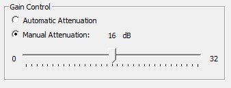
Sodera LE Capture Options Gain Controls
The AT1 through AT3 attenuator values will depend on the DUT1 and DUT2 transmitter Class or the transmit power from each device. At higher power levels all three attenuators may be needed. In all cases, use good engineering practices to protect the devices under test and the Sodera hardware from damage, and to ensure reliable operation.
Using the signal levels as in the example above for the Wired input setup, 2.5 mW will appear at the Sodera LE Antenna connector, again assuming that no attenuators AT1 through AT3 are being used. You can adjust the Manual Attenuation to adjust achieve reliable packet Recording and Analysis. As an alternative, you can also try using the Gain Control Automatic Attenuation option that will adjust the received signal level for estimated best reliable analysis results.
Note: Each Sodera LE Manual Attenuation setting must be configured prior to Recording.
